You followed my miniquad parts list or bought your parts and want to put it all together now? This miniquad build instructions will cover the whole build process, starting from wiring your motors and ESCs to the PDB and hooking up your Naze32, FPV and OSD.
This build tutorial was made possible by Edi from multirotor4fly.com. He is the one and only place you should go if you are looking for multirotor parts in Israel.
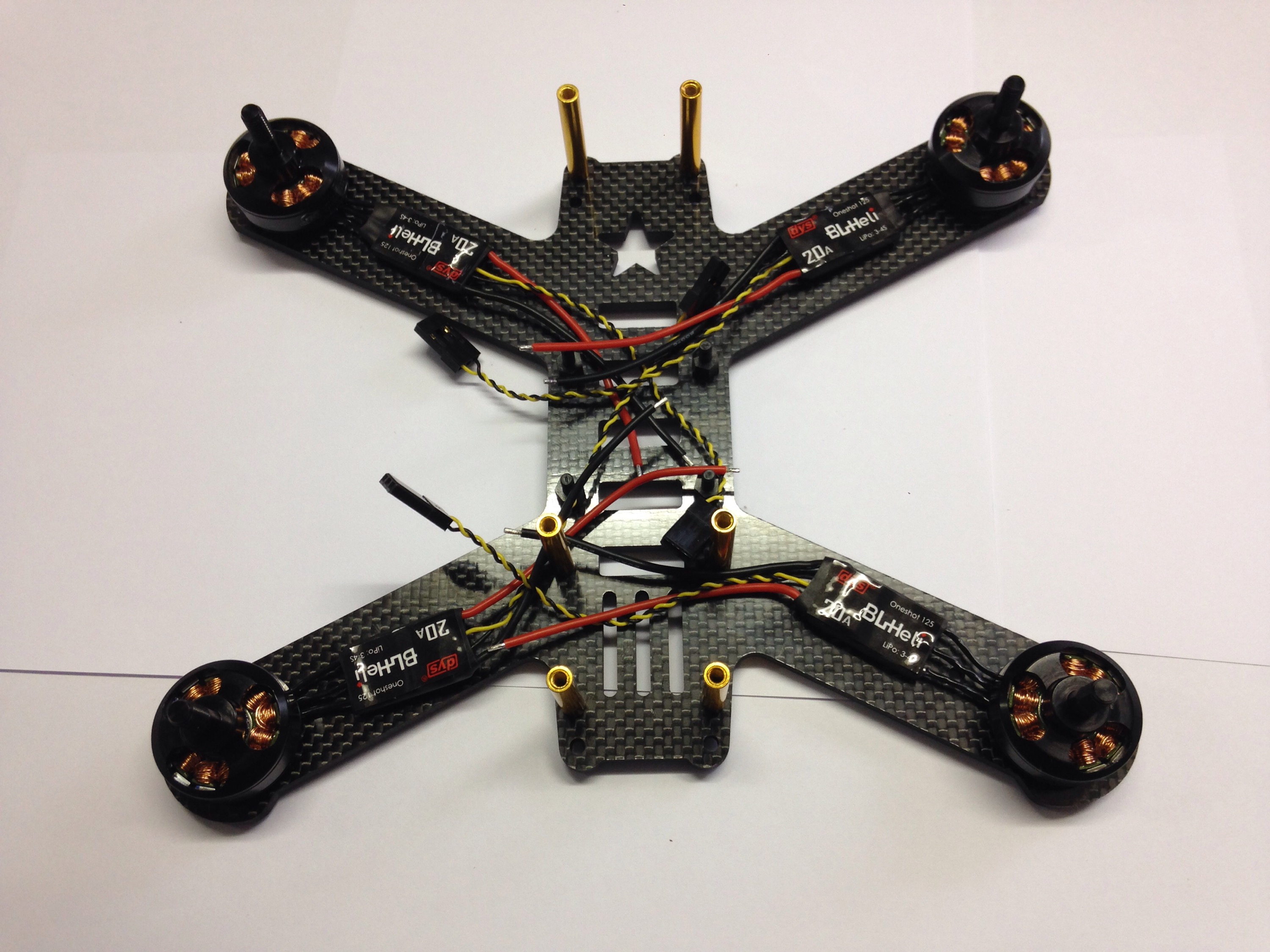
There’s no reason naming the parts since they are all fairly similar from one build to another. Your parts are different than mine, but they should hook up similarly!
Motor & ESC
Put a motor on one of the frame׳s arms to measure the required wire length. I prefer taking off all wire extensions both from the motor (Cobra motors might come with a wire extension) and ESC.
Remove wire extensions
Solder directly to ESC
Cover with heatshrink and use the sticker from the original one
repeat the process for all motors
Mount the motors and ESC to your frame using lock-tight on the bolts
don’t apply too much lock-tight and don’t use too long of bolts
Done with the motors and ESCs part
PDB – power distribution board
Start by soldering the battery lead to your pdb. It’s always smart to solder the thicker wires first.
Using another lead with opposite XT60 helps spread the heat and keeps you from melted XT60s
Solder PDB pins you plan on usingI use double sided foam tape to dampen the vibrations and keep the esc from bouncing on the carbon armsSolder your ESCs to the pdb
Naze32 & peripherals
Solder pins like pictured. This allows you to minimize everything and keep a tidy build
Example of good and bad solders on pins. Bottom left: bad solder joint, pin only attached to one side of the board. Bottom right: good solder joint, solder flowed on both side of board
Connect your buzzer. I like using JST and servo cables to connect everything to my naze32
Voltage sensing: Using a JST (red connector) connect VCC (battery voltage, from the ESC pads) to the VBAT pins on the naze32.
Power the naze: using a JST cable connect 5volts to an unused motor input (5 or 6)
LEDs: using a servo wire connect the voltage for the LEDs to the other unused motor output. Solder the signal for the LEDs to pin 5 on the Naze. I used a buzzer combined on a LED strip, that’s the JST cable you see.
Receiver: Im using PPM, so i use pin 1. If you use SBus or any other serial receiver, solder to pin 4). Jump pins 3-4 for ppm, on this specific receiver!
OSD – on-screen Display
The PDB in this build allows connecting the Video transmitter, camera and OSD fairly easily.
Micro minimOSD: Solder 2 wires from the osd Vin and Vout to a 4pin servo connector
Solder a 6pin header to the OSD and wire a 6pin (or 4) servo connector like in this image (and the previous)
Connect OSD-RX to naze32-TX (pin 3)
Connect OSD-TX to naze32-RX (pin 4)
Connect the camera and vtx to voltage according to your camera specification and wire camera video signal to vtx through your OSD (this pdbs does that for you)