On Screen Display, OSD, allows you to see flight data from the flight controller, on your video feed. Displaying the battery voltage, flight mode, timer, and Name can be useful. There are two possible ways to do so.
In short, the current Naze32 rev5 (and rev6) has only 2 UARTs. These are used to communicate with “stuff” outside of the Naze32 board. For Example, USB connection is on UART1, and it allows to communicate between the PC and the Naze32.
You can get a Micro MinimOSD from here.
When connecting an OSD, it required a UART as well. Since there are 2 UARTs, we have two options.
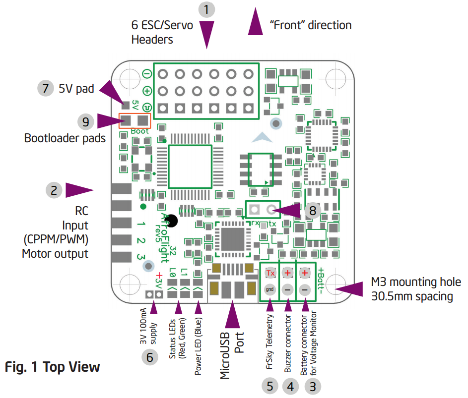
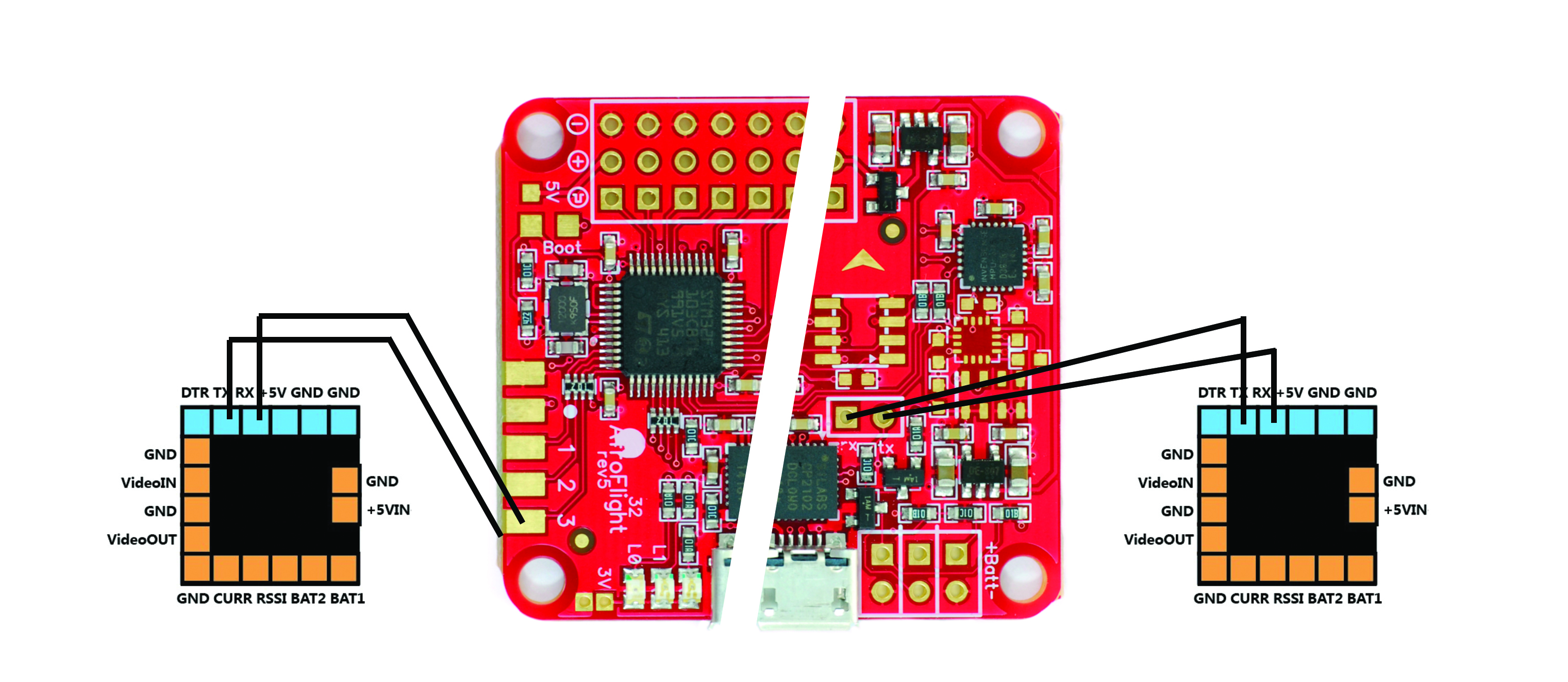
Connecting OSD on UART1 (#8 in Fig. 1):

This way we will connect the OSD with the USB onto UART1. Since a UART can only communicate with one “thing” at a time there will be a “problem”. While connected only by USB, the communication through UART1 will be fine, since only the USB is using it (Assuming the OSD is powered by one of the unused motor outputs).
When connecting the battery to your miniquad (for radio check, or ESC calibration), the OSD will power ON and try to use UART1 as well. In this case, connection to the Cleanflight Configurator will be lost.
In order for this to work, connecting both power and USB, you will have to disconnect the OSD.
A solution will be,
Connecting OSD on UART2 (pins 3-4, #2 in Fig. 1):
Connecting the OSD onto UART2 will separate it from UART1 and the USB, thus allowing to connect both power and USB without worrying about the OSD.
UART2 on the Naze32 is located on the RC input pins 3-4 (Tx-Rx respectively) [Naze32 Tx connects to OSD Rx, and Naze32 Rx connects to OSD Tx]. For this to work you will have to use PPM as a mean of communication with your Radio receiver, since PWM uses all 8 pins for the channels, and S.Bus uses RC input pin 4.
In addition you will have to enable MSP on UART2 through Cleanflight configurator, Ports tab.

My opinion is that since PPM is not “that BAD” even though it is slower than S.Bus, i prefer using it and connecting my OSD to UART2. when Naze32 will have another UART (3) i will move to the faster S.Bus.

On first picture above, connection to UART2 will be to pin 3 and 4, now look like 3 and 8. Question: have you heard about resistor on rx or tx line UART1 to automatic disconnect OSD when USB is plugged?
The image is just to illustrate to where the OSD is connected to, but thanks.
Regarding the resistor on rx or tx, i’ve never heard of it! if you have a link to where you read about it I am interested to read more.
oy! so what happens to GPS? where do we get that to communicate?